


Going further on the Northern line

Project overview
A catalyst for transformation
At 5.28am, 20 September 2021, passengers boarded the first service ever to run from Battersea Power Station in south-west London, on London Underground’s Northern Line Extension (NLE). Construction of our design was completed within six years and delivered a 3km extension to the Charing Cross branch of the Northern Line. The £1.1bn investment also provided two new stations, at Nine Elms and Battersea on the project that saw us providing ongoing support to the contractor until June 2022 to optimise its performance.
The area on the south bank of the River Thames west of Vauxhall was previously poorly served by public transport, unconnected to the vast London Underground metro system. The new stations have changed that. But they are far more than transport nodes – they’ve been catalysts for economic and social transformation.

The underground line extension runs beside the river Thames, from Kennington to the site of the former Battersea Power Station, the preserved four white chimneys of which are visible top centre

Construction of Nine Elms NLE station
Rapid, easy transport was essential to regeneration plans for the area, including the iconic but derelict power station. Regeneration plans justified investment in extending the Underground. And building the extension has unlocked investment in development. The refurbished former coal-fired power station and its immediate surroundings will be home to about 298,000m2 of office, retail and leisure space as well as a new riverside park, with computing giant Apple occupying six floors in the redeveloped power station. The US embassy relocated to Nine Elms in 2018 and the nearby New Covent Garden Market is being reconfigured to create a thriving, modern food quarter for London.
Overall, the extension is forecast to boost London’s economy by up to £7.9bn, with about 25,000 jobs and 20,000 homes created in the area. Better accessibility and quicker journeys alone will contribute about £1.5bn. Environmental benefits include improved air quality as people switch from using other forms of transport.
£7.9bn boost to London economy
25K forecast jobs
20K new homes
There are many challenges involved in expanding transport networks in congested urban environments, above and below ground. Budget, space and time constraints, and the need to protect existing assets all demand innovative methods and different ways of working. As lead designer on the project, working for main contractor FLO – a joint venture between Ferrovial Construction and Laing O’Rourke – we helped to overcome these restrictions to deliver sustainable solutions for the NLE.
Our role included civil, structural, mechanical, electrical, public health, architectural and rail systems design, and systems integration services. Our company founders, engineers Basil Mott and David Hay would undoubtedly have been excited and proud: both worked in the late 1880s on the construction of the City & South London Railway, from which the Northern Line evolved. It was the world’s first deep-level rail line and one of the first to use electric power.
After an incredible effort from the huge number of people who worked on this project, the two new stations at Nine Elms and Battersea Power Station are open – the first new stations on the Northern Line for 80 years. They will hugely improve connectivity between these areas and the rest of London, and play a major part in the capital’s recovery from the pandemic by supporting thousands of new jobs, homes and businesses.Sadiq Khan
Mayor of London
An early warning pilot
Space is often at a premium in urban construction projects and Battersea and Nine Elms stations were no exception. It was about using the right tools for tight spaces.
Digital tools and alternative construction solutions helped to address the space challenge on the NLE. Building information modelling (BIM) and design for manufacture and assembly (DfMA) were both used extensively, possibly more so than on any other transport project to date.

Battersea NLE station construction site
BIM is the process for digitally creating, managing and sharing information on a construction project. The design is a virtual representation of the real asset, in which the attributes of every asset are known: materials, supplier, structural properties, cost, carbon, maintenance and replacement schedules, and much more. BIM enables all design disciplines, third parties and stakeholders to collaborate and access a single source of information through a managed common data environment (CDE).
On the NLE, BIM aided multidisciplinary working by improving collaboration through intelligent 3D models and data exchange. Design information was shared through the CDE, enabling all involved in the project to exchange data and ensure their contributions and requirements were visible to all.
Model benefits
During the design and construction phases of the NLE, BIM enabled interrogative checks to remove potential clashes between the contributions of different design disciplines. Operators and maintenance crews could check the designs for ‘real world’ practicalities like access, materials handling, public safety and ease of cleaning. Emergency services could check firefighting and crowd evacuation. And FLO could plan and rehearse construction sequences.

Model for Battersea NLE station
BIM was also used to assess the impact of building and operating the NLE on communities, through acoustic modelling and line of sight analysis, for example. The workflows embedded in the CDE provided assurance and an effective tool for auditing. The hosted files contained information on purpose – compliance, construction or planning – and suitability and status, such as particulars requiring comment or approval.
Long-term, BIM will help asset owners manage and maximise performance. Both stations on the NLE were delivered using the UK government’s BIM level two compliant methods, providing London Underground and the capital’s transport agency Transport for London (TfL) with a database to manage the assets efficiently over their 120-year lifespan. “When objects designed using BIM, we know what they do, what they’re made of, how much space they take up, and how often they need maintaining,” explains Robert Dickson, NLE project manager for Mott MacDonald.
Ensuring everything fits and works together in a virtual environment during design saved time and money later. Issues and discrepancies were visible and could be remedied in the model during design development, avoiding the need for costly alterations during construction, which is all too common on many major projects.Nicola Ballarin
Design manager
Factory built: design for manufacture and assembly
Working closely with FLO, we developed DfMA modelling best-practice guidance and a series of underlying design protocols to ensure the benefits of design for manufacture and assembly were maximised. DfMA helped greatly in confined working environments, particularly at Nine Elms, with space freed during construction by using precast beams and other prefabricated components manufactured offsite. This reduced the time on site devoted to concreting and improved quality control. The beams prop up the walls of the Underground station boxes, which hold back substantial ground pressure, as well as supporting the stations’ floor and ceiling slabs equipment including lifts, escalators, and ventilation equipment.


DfMA was used extensively on the Northern Line Extension
Precast coffered slab units at Battersea NLE station
Beam to column junctions: isometric of beam to column junction (top left); typical integration of cabling at beam to column junction (top right); typical insitu stitch at beam to column junction (bottom)
The station features a precast frame
Virtual virtuosity
Visualisation tools, such as virtual reality (VR) and augmented reality (AR), can be used to explore computer-generated environments, and we developed and tested both applications in the NLE design process.
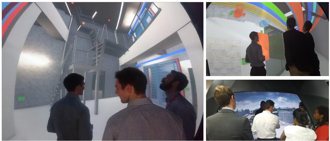
VR enabled digital walk throughs by stakeholders to review designs and explore what buildings and areas would look like and how people might use them. By scanning a QR code, barcode or stamp on traditional 2D drawings, viewers could view a perfectly synced and scaled 3D digital model, using a tablet or phone. The model appeared superimposed on the drawing and enabled users to view and understand it both more intuitively and in greater detail.
Development above the stations
Development is still under way above and around the Battersea and Nine Elms stations. Three triangular towers ranging in height from 74m to 89m are being raised up on a podium, above the station box at Nine Elms. These will contain 479 ‘build to rent’ homes – 40% of which will be categorised as affordable – with associated services and amenity space. A fourth building alongside the station will contain commercial and retail spaces. Oversite development above the Battersea NLE station will form part of a mixed-use precinct of residential, retail and commercial units and a new park.

Vertically profiling radar calibrates the permanent C-band radars operated by the city

Top-down frame construction
Both stations are in boxes that sit 20-25m below the surface and form part of the foundations for the overlying structures. To speed construction and avoid extensive temporary works, top-down construction methods were employed to build the station boxes. This technique enabled the foundations and superstructure to be built simultaneously. In a further move to save time, design of the secondary structure and initial construction of the primary works (the shell of the box) at the stations and shafts ran in parallel – the stations were still being designed as the first piles were bored. This enabled construction to start less than one year after the detailed design work began.
At Battersea, the grillage of capping, propping, spine beams and columns supporting the station box walls, floors, roof and, ultimately, three tower blocks to be built above, were constructed as excavation of the station box advanced: temporary and permanent works rolled into one.
Emma Hale was manager for detailed design of the station at Nine Elms and says the team had to design the station box and above ground structures knowing that oversite residential developments could be built on top of it in the future – but with limited detail initially about their height, footprint and the loads they would impose. The station box therefore had to be designed ready for any eventuality. “The box has been designed to take the weight of tower blocks more than 20 storeys high. That means the structural elements are really large. Big columns, big walls, larger and deeper piles,” she explains.

Nine Elms NLE station with planned oversite development

Planned OSD at Nine Elms NLE station
The station is an operational asset and designers had to ensure that access and maintenance was built into the design from the start. The station structure has a 120-year design life, whereas much of the mechanical, electrical and plumbing infrastructure will last for only about 40 years and will need maintaining and replacing.
The size of the box was set once construction started, and access routes subsequently had to be maintained and incorporated into it that were big enough for work to take place.
“Ensuring you can remove tunnel ventilation fans that weigh in excess of 10t and are located 15m below ground is a challenge,” says Emma. “Space is always at a premium given the number of services required for a station.”

Nine Elms NLE station at its opening
Battersea NLE station presented an even bigger challenge. The footprint for buildings above the terminus changed from the original masterplan, explains lead engineer Ian Watkins. “This required us to work closely with the station architects [Grimshaw], developers and contractors to develop an integrated, workable solution. It was also important to ensure the existing surrounding community can access the new facilities, including the new park adjacent to the entrance,” he says.
A strong ‘transfer deck’, supported on the station’s grillage structure, will carry the buildings above. Our engineers designed the grillage with beams of varied depth, providing the load-carrying muscle, but also saving space within the stations. This variation in beam depths saved hundreds of tonnes of concrete and steel. Ian says the design of the structural elements was not straightforward: “One of the towers sits at 35° relative to the grillage of the station box, for example, so few of the building’s columns line up with the station’s.”

Battersea NLE station at its opening
He also outlines how delivering the remit for widespread access required us to design a station with two entry and exit points rather than the single entrance initially proposed by London Underground.
Battersea NLE station was built within diaphragm walls made of reinforced concrete panels. The design used what geotechnical engineer Peter Rutty describes as a “trouser leg arrangement”, with alternating long and short panels. Long panels are 56m deep, excavated through London clay and toed into Thanet sand. The shorter panels stop within the clay. Thanet sand provides firm structural support. In addition to steel ‘plunge’ columns founded in reinforced concrete piles, the long panels play a key role in supporting the over-station development. The short panels transfer their share of the load to their longer neighbours.
“It really speeded up construction,” says Peter. “A deep panel takes up to five days to make. Shorter ones only two or three days.” Importantly, the arrangement also reduced excavation volumes and the amount of concrete used by 30%.

Largest crossover in London at Battersea NLE station
At Battersea the largest crossover in London was constructed adjacent to the station. A crossover allows trains travelling in different directions to change tracks. Like the station, the Battersea crossover is housed in a box that was used to launch the tunnel boring machines (TBMs) for the main running tunnels. Construction support lead Chris Lile reports that our adoption of the observational method (OM) – which involves monitoring movement in real time between soil and structure – allowed the crossover box to be excavated using one fewer layers of temporary supports than the construction methodology anticipated. “The OM demonstrated ground movements were less than the initial design predictions, allowing the removal of a layer of temporary propping. This reduced congestion in the box, allowing excavation to advance faster, and saved around £1M.”
Noise control
Disturbance from ground-borne noise and vibration from railways is an increasingly challenging, costly and policy-driven problem in the industry.
At 35dB(A) in nearby residential properties, noise limits for NLE were particularly strict – the line must be inaudible in people’s homes at any time of day or night.
Railway noise and vibration originates from steel wheels running on steel rails. Although the steel may look smooth to the naked eye, wheel and rail surfaces have a texture measured in micrometres, which causes vibration, in turn causing noise. Tunnel ventilation fans can kick out a lot of noise too. “At full power, the noise of a fan is similar to that of a small jet engine. But with careful design, the noise isn’t really noticed. In normal operational mode, most noise inside a station is from trains. Fans are most noisy in an emergency,” says Simon Kahn, technical director of acoustics at Mott MacDonald.

Vibration can be transmitted to the tunnel structure into the surrounding soil. Operators around the world have used different methods to control the problem. The Paris Metro uses rubber tyres, which results in a smoother and quieter system, while Maglev or magnetic levitation trains do away with wheels and rails altogether. On the NLE, noise levels are controlled by using trackforms known as rubber-booted sleepers. The rubber boots are shock-absorbing pads that damp vibration.
We used our in-house ReVERB software to model NLE train vibrations and noise levels to predict their peak and cumulative impacts in residential areas, specifically the effects on people, rather than damage to buildings.

ReVERB enabled us to consider all types of buildings, soil variations, tunnel structures and train speeds among other variables for the full running length of the line
We were also able to test various trackforms ensuring the booted sleepers would provide adequate noise control to meet the strict specification. It was a radical departure from the traditional approach, which relies on repetitive, discrete and often error-prone calculations. By comparing and validating our predictions against real measurements taken on the nearby Victoria line, ReVERB on NLE set a new benchmark for ground-borne noise and vibration prediction.
Absorbing energy
The walls of older Tube stations are usually tiled. These create echoes. “You need to test every scenario, including the acoustics and intelligibility of spoken warning systems,” Simon notes. To achieve good acoustic performance, porous metal panels over a mineral wool are used in newer stations to absorb sonic energy and improve acoustic performance.

Mineral wool was used for the NLE stations and ventilation shafts to minimise noise, helping the line to be a good neighbour to local residents
Our engineers engaged with the design team at the beginning of the project so that noise insulation was factored in from the start, not squeezed in after important architectural, structural, operational and mechanical decisions had been taken.
Going underground with Helen and Amy
Two TBMs bored largely through London clay to construct the twin tunnels linking the Kennington shafts at one end of the NLE with Battersea station at the other.

The TBMs, called Helen and Amy, were 6m in diameter, more than 100m long and weighed 295t. They were lowered 25m into the crossover box at Battersea NLE station and began their work in April 2017. Helen was named after first British astronaut Helen Sharman and bored 2.6km to Kennington Park to create the southbound tunnel. Her sister TBM, Amy, was named in honour of aviation pioneer Amy Johnson, and travelled 2.4km to Kennington Green to form the northbound tunnel.
Each machine, operated by a team of about 50, tunnelled up to 30m a day for around six months. Helen and Amy excavated more than 300,000t of material and installed almost 20,000 precast concrete segments to form the tunnel linings. A conveyor system took the spoil from the tunnels to barges on the River Thames, which ferried it to a former landfill site in Essex to create arable farmland.
2 tunnel boring machines, called Helen and Amy
20K precast concrete segments forming 4000 rings lining the tunnels
3km data points processed each day
There is a jumble of existing infrastructure in the ground under much of London. Avoiding gas pipelines, electrical cables, water mains and sewers requires accurate data and clever design. Design manager Nicola Ballarin worked on potential damage assessments (PDA) for utilities and structures affected by the tunnelling for the NLE. To assist the PDA, we compiled a database of underground London assets. One piece of infrastructure that had to be avoided was Thames Water’s London ring main, supplying water to half the capital’s population. It runs very close to the Battersea station box.
BIM was used to create a virtual construction model of the tunnels that FLO used for weekly briefings with stakeholders including Thames Water, Network Rail and London Underground. FLO developed the model further as tunnelling work progressed, using it to assist site delivery teams, and conduct health, safety, environmental and quality assessments.
Saving carbon... and money
The CEEQUAL sustainability framework for civil engineering and infrastructure was used by TfL to drive sustainable design and construction on the NLE.
Our engineers worked with FLO to identify potential material and carbon savings. They found that reducing the thickness of the tunnel linings by 30mm, from 280mm to 250mm, saved about 2700m2 of concrete and 1500t of carbon. This outcome followed a reassessment of the geology and refining the structural design of the segmental lining by the design and construction teams.

Reducing the thickness of the tunnel linings by 30mm saved about 2700m² of concrete
Replacing ordinary Portland cement with alternatives, such as ground-granulated blast furnace slag (GGBS) from steel manufacturing, produces concrete with lower embodied carbon. On the NLE, we used concrete for secant piling with 95% GGBS – much higher than the norm. It reduced embodied carbon by 80% compared with conventional Portland cement. The slag-based concrete was carefully designed to optimise the performance of fresh and hardened concrete, including its long-term durability, and minimise the environmental impact.
Adopting a more sustainable approach has financial as well as environmental benefits. As part of our multidisciplinary design role for Crossrail on the Elizabeth line in London, we collaborated with manufacturers and future asset operators on LED lighting for new underground tunnels and stations in the central section. LEDs will produce significant whole-life cost and carbon savings compared with conventional lighting – £2.4M in energy savings and 23,400t of carbon.
15t of carbon saved by reducing tunnel lining thickness
£2.4M energy saving from LED lighting
Joining new tunnel to old
At Kennington station, where the NLE meets the existing Northern line, the new tunnel had a substantially larger diameter than the old one and was built around it.
On completion of NLE tunnelling, the old segmental iron lining was dismantled, and a clean join constructed between the two – known as a step plate junction. Optimising the tunnel alignments reduced the length of the overlap between the new and old tunnels by about 40m, saving valuable construction time and costs, and enhancing safety.


Removal of old iron tunnel lining
Kennington step plate junction
The considerable reduction in size of the step plate junction tunnels also had the following beneficial consequences:
- Reduced excavation area/length helped reduce ground settlement and volume loss in the area, minimising impacts on buildings, utilities and the existing tube tunnel
- The reference design generated very large movements and would have required compensation grouting and the construction of temporary gallery tunnels 150m long and up to 4.5m diameter during the permanent step plate junction works. Instead, the final design reduced the maximum settlement, enabling FLO to build the junctions without the need for compensation grouting.
Letting the Underground breathe
Tunnels and Underground stations must be well ventilated. Ventilation shafts across London act as the lungs for the London Underground network, although you might not know they are there: many are disguised as buildings.


Models for Battersea NLE station
Models for Battersea NLE station
The NLE has introduced two new additions to this largely hidden aspect of metropolitan life. The northbound tunnel is ventilated at Kennington Green and the southbound tunnel at Kennington Park. Both ventilation shafts have head houses, blended in with the local neighbourhood using brickwork that matches houses in the area.
Shaft design lead Andrew Evans says addressing the concerns of residents was as important as the engineering: “Our in-house environmental consultants, together with TfL and the architect, Grimshaw, worked with FLO and LU to consult widely with Kennington residents. TfL was keen to incorporate bird boxes at the Kennington Park head house. We liked the idea and led a feasibility study to ensure they would work and that the birds wouldn’t be in danger if there was ever a fire.”

The ventilation shafts at Kennington
Both ventilation shafts house giant fans to get fresh air into the tunnels and pull smoke out in the event of a fire. They comprise a cylindrical flue from tunnel to surface, and a long, horizontal box for the electrical equipment that powers axial fans blowing air, or pulling smoke, through the tunnels. Support is provided by secant piled walls and internal blockwork. The external secant piled wall structure was coated with a sprayed concrete and an internal lining wall to make it waterproof.
Tight squeeze
Ventilation shafts double as escape routes. “We had to use confined areas as efficiently as possible,” says Andrew Evans, who co-ordinated the design for the NLE shafts at Kennington. “It involved juggling all the systems that can and can’t go next to each other, such as the primary and secondary power cables from track to surface that cannot follow the same route in case of damage from fire. You also have to design for different access and egress routes. You have limited space to work in a shaft, so it can be a challenge squeezing everything in.”

A slice through time
The NLE has been built in an area of the Thames riverside that was formerly marshland, channels and gravel islands. These were associated with the Battersea Channel, a relic river channel that existed in the wider Thames floodplain. The environment made for an ideal hunting ground for our prehistoric ancestors, with former archaeological investigations revealing evidence for Late Mesolithic (7000 BC to 4000 BC) and Neolithic (4000 BC to 2200 BC) communities.

Several posts were discovered, and soil cores such as these were taken for environmental sampling, providing a ‘slice through time’ over 8000 years
Over time the channels filled with sediment (alluvial and peat deposits) forming waterlogged conditions where organic remains, such as wooden posts and fish traps, could survive from this distant past. These deposits were deep, buried under modern developments.
At both Battersea and Nine Elms, construction of the station boxes and TBM launch pits required deep excavation, allowing the removal of ancient artefacts remains. Archaeologists from the Museum of London archaeological service conducted the exploration.
Systems integration engineering
A station is complex, and systems integration is the glue that binds things together. It gives clients confidence that the design will meet their needs. The role of systems integration engineers is crucial to knitting together components and ensuring they work.
Our systems integration engineers working on the two new NLE stations liaised with suppliers of services and equipment. These included signalling, ticketing systems, radio communication, power supply and monitoring, rolling stock, station advertising and station systems, such as a local area network, WiFi, telephony, CCTV and public address and voice alarm equipment.


MEP, fire, tunnel ventilation: what goes where? Visualising all the station systems
A sum of its parts: Kennington ventilation shaft
Shaft design lead Andrew Evans says addressing the concerns of residents was as important as the engineering: “Our in-house environmental consultants, together with TfL and the architect, Grimshaw, worked with FLO and LU to consult widely with Kennington residents. TfL was keen to incorporate bird boxes at the Kennington Park head house. We liked the idea and led a feasibility study to ensure they would work and that the birds wouldn’t be in danger if there was ever a fire.”
Our systems integration engineers hosted dedicated BIM review workshops for suppliers, presenting 3D digital plans, and held co-ordination meetings on different aspects, such as the cable management system. They had to consider the footprint of equipment as well as the space required for maintenance access. To design the substation and transformer rooms on the NLE, we used detailed 3D design, even down to the location of electrical sockets. In the model, you can identify all the equipment – doors, walkways and signage as well as electrical kit. London Underground received the model and all the data within it – a digital twin of the NLE – at project handover.